STEERING KNUCKLE REMOVAL and BALL JOINT REPLACEMENT
Here's a step-by-step guide to removing
the steering knuckle, in case you need to replace your wheel bearings or ball
joints. The pictures below are with the strut assembly removed as I am doing the
entire suspension work at the same time and had just removed the struts.
Tools Needed:
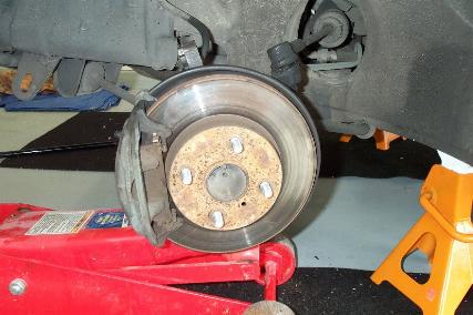
1) Loosen wheel nuts. Raise and support front of car, and remove wheel.
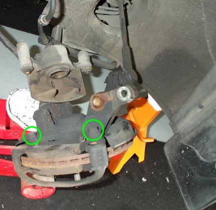
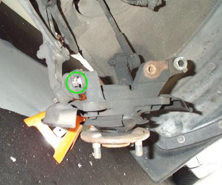
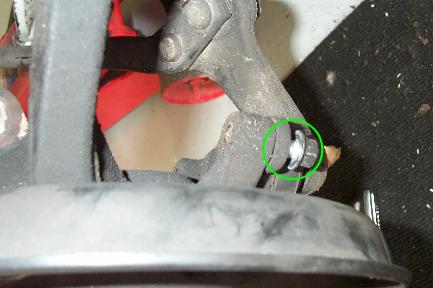
2) Remove caliper by the two 12mm bolts. Then remove
the two 17mm bolts that attach the mounting brackets to the steering knuckle,
indicated below. Remove the mounting bracket and brake pads from the brake disc.
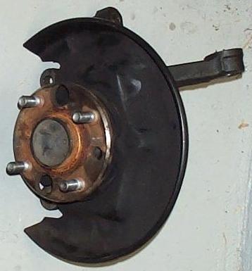
3) The disc should then pull off.
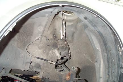
4) Hang the caliper from the strut assembly, or if
you removed the assembly like me, then hang it from the strut top bolt holes in
the frame. This is so you don't put any tension on the brake lines.
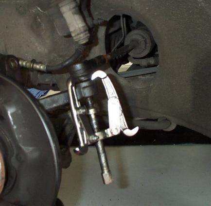
5) At this point, I would remove the tie rod end from
the steering knuckle. If you have the strut assembly in place, the hub is
solidly in place. (I probably should have done this before removing the strut
assembly to make it a lot easier.) Anyway, remove the cotter pin and 17mm bolt
from the bottom of the tie rod end. Attach a 2 or 3 jaw puller to pop the tie
rod out of the steering knuckle.
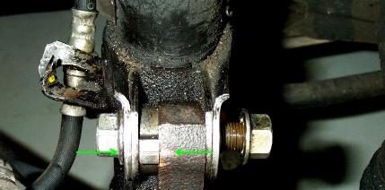
6) Scribe a mark in the strut bracket to indicate the
current camber position. (Ignore the loose bolt and the brake line.)
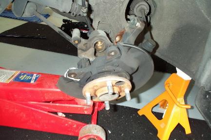
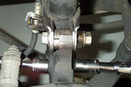
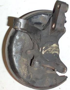
7) Remove the steering knuckle from the strut
assembly, two 17mm nuts/bolts. (Ignore the brake line.)
8) Remove the two 14mm bolts that hold the knuckle to the ball joint.
The steering knuckle should then fall in your lap.
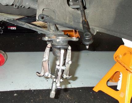
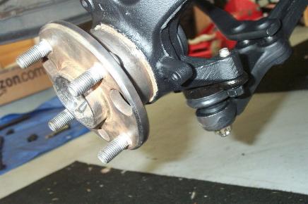
9) If you want to replace the ball joints remove the
cotter pin and castle nut, and attach jaw puller. Beware, the ball joint will
literally POP out of the control arm, so keep away from inside the inner wing while you tighten it down.
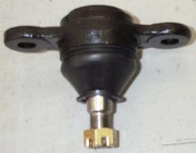
10) Here's the new ball joint:
11) Bolt it onto the steering knuckle.
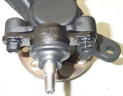
12) Now, place the steering knuckle onto the control
arm and tighten down the castle nut. Insert new cotter pin.
13) The rest of the assembly is opposite the removal.
Various sockets, spanners and ratchet
2 or 3 jaw puller
Jack and stands