DESIGN AND MAINTENANCE NOTES - STARTER MOTOR SYSTEM.
This article is intended as the first of a series of items
covering the main systems of the car, with the aims of providing a brief guide to:-
- design features
- good and bad reliability aspects
- hints and tips on key maintenance jobs
This sounds simple enough to do but the hard bit is to balance technical
content with 'readability' - too little detail will leave 'holes' which might be
important to those doing their own work - but too much could be too lengthy and
just plain boring to others.
There are quite a lot of subtly important aspects which are not covered in
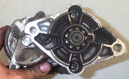
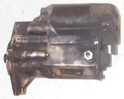
any of the manuals - to include them in one article could fill many pages of
this magazine - to the extent of spoiling its readability.
So, I have deliberately kept this article brief, but with hints on pitfalls
to watch out for. Fuller details can then follow in a later issue - or possibly
on the website.
System design details
The system design is utterly conventional – the ignition switch feeds the
starter motor relay which feeds the solenoid on the pre-engaged starter motor –
just the same as is fitted to millions of modern cars and is well proven.
The circuit diagram is ---
At a detail level it is the starter motor itself which is different to most
other makes - the MK1 uses a reduction gear between the motor and the drive
pinion. This allows a better motor performance albeit at the cost of slightly
more complication.
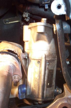
It also makes the assembly less bulky than normal - allowing Toyota to tuck
it out of the way - almost to the point of hiding it! More than a casual glance
is needed to spot it - lurking underneath the exhaust manifold. There is
negligible maintenance access from above, and the compactness plus working on it
from below make life a bit harder than normal.
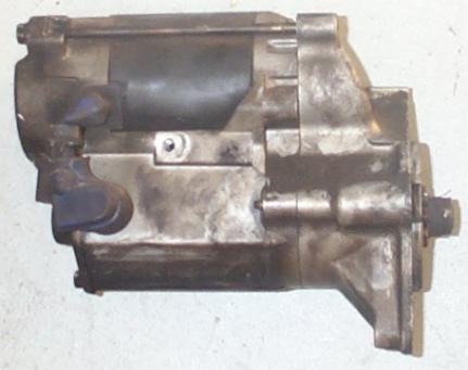
An exploded view of the starter is--
The relay is located in the nearside junction box near the front of the
engine compartment.
Reliability
The system is well - proven and reliable. I rarely get queries on it, and it
seems to be good for 100k miles+. In my case the motor started showing slight
signs of weakness after 112k miles, so I ended up changing it. The following are
brief notes on changing it --
Removal
This is not the most convenient job - it needs to be done from underneath
with the n/s rear jacked up and propped.
1) Make space to be able to maneouvre the motor out downwards. Removal of the
exhaust front pipe would be ideal, but too much hassle & not essential. The
plastic undertray really does need to come off - about half a dozen M6 bolts to
remove. These are often seized & rounded - I've had to drill the odd one
out.
2) Disconnect the battery negative lead. Whilst I would normally avoid this
if at all possible, the risk of not doing so is a bit high - one of the leads on
the starter motor body is a permanent unfused lead from the battery positive.
This has to be undone with a spanner, and any accidental contact to earth with
this spanner will cause a significant short which could burn the wiring harness
out - or worse. There is just not enough clearance in this area to take those
sort of risks.
The unfortunate downside of disconnecting the negative lead is that the ECU
will lose its 'learnt' adaptive memory. This is another story for another
article - but is not the end of the world - it reverts to the factory default
setting when connected up again. What it does mean is that it will then take a
couple of dozen typical journey cycles to 'relearn' and re-optimise the ignition
timing etc. - a minor nuisance. Any radio security coding is obviously also
activated.
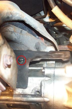
3) Remove heatshield - this is not essential at this point but it makes the
motor assembly a bit smaller for getting out. It is held by one 6mm bolt -
remove with a 10mm 3/8" drive socket.
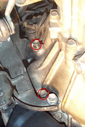
4) Slacken the two mounting bolts for the motor. These are both 14mm across
flats -the lower one is easily visible but the upper one is tucked away under
the clutch slave cylinder.
5) Remove the bolts - usually hand spinnable. Keep motor supported by free
hand - its not unduly heavy.
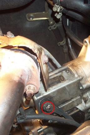
6) Undo the 2 motor connection leads. (These cannot be undone with the motor
in position as they are too close to the block to get at.) The permanent
positive is a 12mm A/F nut, the ignition switch live is a plastic plug. The
latter has a bayonet catch on it which has to be depressed with a screwdriver
blade to release it.
7) Manoeuvre the motor out past the bottom of the exhaust manifold - its not
unduly tight for clearance.
CHECKS
Having got the motor out there are a limited number of checks that can be
done - the brushes, commutator, armature, coil and solenoid resistance. However,
apart from brush changes none of the parts are readily user replaceable. Even a
brush change is of limited value as the commutator will be worn.
All in all, given the time needed to remove and replace the motor, I elected
to fit a reconditioned unit - available from motor factors such as Partco,
Halfords etc. (Not cheap at £90 - but that`s also the going price for a 'common'
unit such as for a Metro or Corsa.)
One point to note if getting a reconditioned unit - check there is a threaded
hole in the body to mount the heat shield. Mine didn't have one so I
'improvised', but it took a couple of hours.
REPLACEMENT
Just reverse the steps for removal, take care that the motor sits squarely
home on its seat when bolted up. Listen carefully when first starting to check
the meshing sounds OK - if not re-check the motor unit seating.
For those that are feeling really conscientious, after a couple of days
re-nip up the mounting bolts as a precautionary measure.
This gives a brief flavour of the system and working on it – I`ll endeavour
to write a full description for a future issue.
ALAN JONES
Starter Removal and Rebuild
After just hearing a click when turning the key to start the
car, I had to rebuild the starter. Here's how you go about replacing a couple
contacts and the brushes, which should bring your starter back to life.
Removal of Starter
1) Raise and support the rear of the car on jack stands.
2) Disconnect the negative cable from the battery.
3) Remove the under-carriage cover (bunch of 10mm bolts). You should then
have ample room to work with the starter. It is right between the front motor
mount and the exhaust manifold.
4) Remove the heat shield from the starter (10mm bolt).
5) Remove the two 14mm bolts on the other side of the transmission.
6) Disconnect the black plug (Terminal 50) on the end of the starter.
7) Slide the starter out of the tranny, toward the passenger side of the
car.
8) Twist the bottom up toward you, so that you can access the 12mm bolt
holding the battery wire to the starter (Terminal 30).
9) Turn the starter counter-clockwise. So that the gear part faces the front
of the car.
10) Then pivot the starter down, so that the gear side comes right down
toward you. It should then slide out of the car pretty easily.
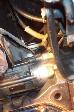
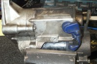
11) Just some pics of the starter.
Removal of Copper L-shaped Contacts
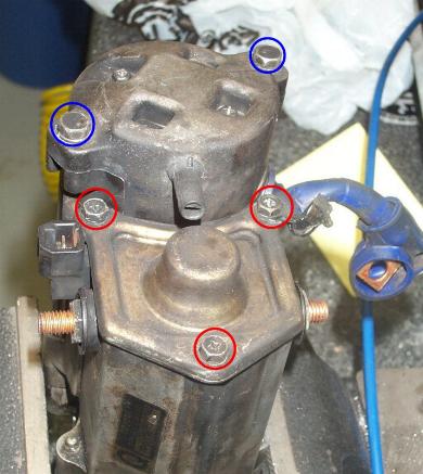
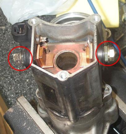
12) Remove the two long, skinny 10mm bolts (blue) holding the field frame and
armature to the starter housing. Pull the field frame up and off. The armature
may come off too with the frame. If so, be prepared for it to fall as you remove
it.
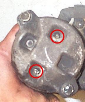
Then remove the three 8mm bolts (red) holding the cap on the magnetic switch
end.
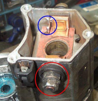
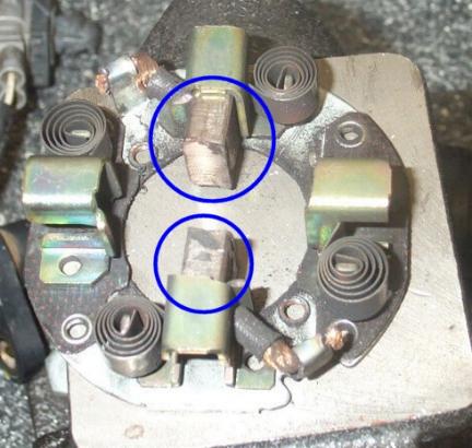
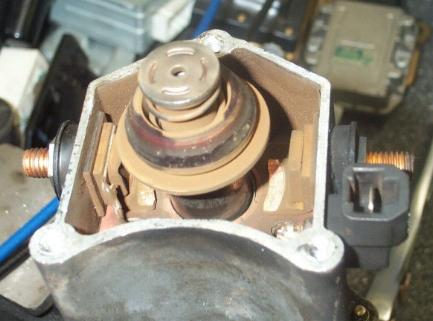
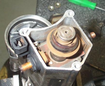
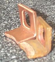
13) Here's what you will see after you remove the magnetic switch end cap.
The plunger in the middle pushes down to engage the gear on the opposite end.
When it does this, the copper ring on the plunger comes into contact with the
copper L-shaped contacts on either side of it. Those are what we are going to
replace.
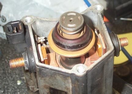
14) Remove the plunger by pulling it straight out. Be careful of a skinny
spring on other end of the plunger. Keep it in a safe place.
15) Remove the cap from Terminal C and remove the 12mm nut holding its ring
terminal on.
16) Remove the various nuts, washers, & insulators that are holding the
L-shaped contacts in place. Take note of the order of how you removed
everything. Be very cautious of the one bolt that has a washer that is connected
to a wire leading down to some windings. The wire is quite brittle, and if you
break it, you will need to solder it back in place. It's no big deal though,
just need a solder gun and a small piece of solid copper wire.
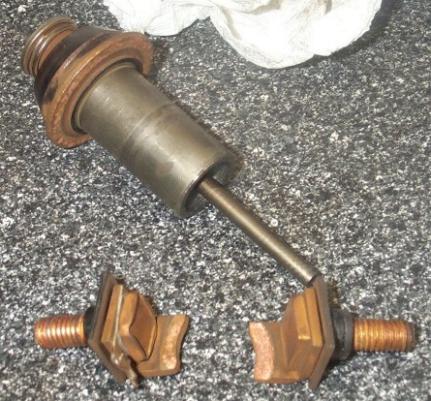
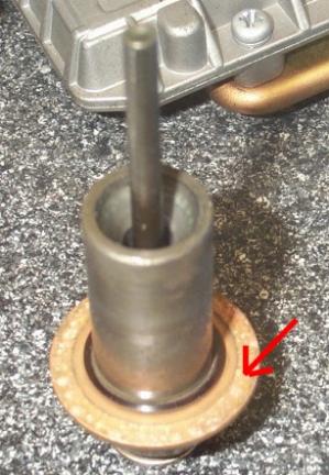
17) Here's the plunger & the copper contacts. Notice the roughness of the
underside of the plunger's copper ring. Sand/file it down, so that it is smooth
again.
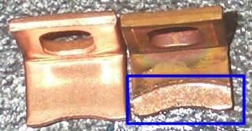
Here's a comparison of the new contacts to the old. You can see how it has
been worn away by the spinning each time the car is started.
18) Just pics of the empty starter housing. You can see I broke that
connection on that washer I was speaking about earlier.
Install New Contacts
19) You can purchase the new contacts at a local starter rebuilder. Just look
in your Yellow Pages for one. I've read a few people on the MR2 message board
have only been charged a buck for both contacts. Well the guy I went to wanted
$9 for 'em. Didn't feel like running all over town so I went ahead with them.
Install the bolts & contacts the opposite of how you removed them.
Noticed the new wire soldered in place.
20) Place the spring and plunger back down in the cylinder.
21) Install the cover and the three 8mm bolts.
Inspecting Brushes
22) If you want, since you have the starter out, you can check the condition
of the brushes. Remove the armature from the field frame. Clean the dirt/grime
off the windings with some fine sandpaper.
23) Remove the 2 Phillips screws holding the cap to the field frame/brush
holders.
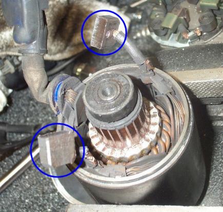
24) You can now see the brush holder 'standing' off from the field frame.
Remove the 2 brushes from the holder that are keeping it in place. They are held
in by spring clips, just take a skinny screwdriver to get them out. You can now
inspect the brushes (sand/file if needed) and check their length. BGB calls for
a minimum width of 10mm. Replace if necessary.
25) Place the 2 brushes on the field frame back into the brush holder. This
may take some time and finesse with a screwdriver...
26) Insert the armature into the field frame. The small coil goes toward the
brushes end. Work the brushes over the bearing and onto the coils. This may take
a few minutes since you only have 2 hands, trying to work all 4 brushes at the
same time.
27) May as well clean the bearing surface and the underside of the field
frame cap. Apply a little bit of fresh grease to the bearing surface.
28) Watch out for the armature falling out from the bottom, and place the
field frame cap over the brush holder. Line up the holes and tighten the 2
Phillips screws.
29) Turn the field frame assembly over and clean up the bearing on the other
side of the armature. Apply fresh grease. Clean up the starter housing where the
armature gear fits into and install it into the starter housing. Make sure the
holes in the field frame cap line up with those of the housing. Install the two
long 10mm through bolts.
30) Connect up Terminal C, and tighten the 12mm bolt. Starter is now ready to
go back in the car.
Installation of Starter
31) Installation is exact opposite of removal.
A lot of steps, but a real easy project. Removal and installation of the
starter should take 15 minutes tops. Keep track of all the bolts, screws,
washers, etc. when taking the starter apart.

![]()
![]()