MAINTENANCE NOTES - EXHAUST SYSTEM
The MR2 exhaust system is a relatively conventional 2 box
system, but being mid engined it has to be squeezed into a much shorter length
than the common or garden front engined car. This creates one or two
complications, but these are minor as will be described below.
Describing the system briefly from the cylinder head :-
a) Exhaust manifold - cast iron, 4 into 2 into 1 configuration. Encased in
sheet metal heat shields due to the close proximity of the cockpit bulkhead and
ancilliaries such as the oil filter and starter motor. Manifold to cylinder head
fixing is by 3 bolts, 2 nuts and a flat face metallic gasket. Manifold to
exhaust fixing by 3 'bolt' flange (- actually studs and brass BSF nuts), with a
spiral wound gasket in spigot and recess.
(Spiral wound gaskets are composite metallic/sealing compound chevrons wound
around each other, to provide a 'spring-loaded' gasket.) This 'spring-loading'
gives the best chance of sealing against thermal cycling and flange misalignment
- common exhaust features.
The outlet flange is restrained by a bracket which bolts into a tapping in
the block. This is clearly to reduce torque induced loads on the manifold and
its gaskets and fixings. The torque load comes from the transverse engine - it
has no choice but to rock fore and aft on its rubber mounts as the throttle goes
on or off. However the downstream exhaust mountings tend to resist this
'rotation' - despite Toyotas best design efforts using rubber mounts. Without
this bracket the engine and the exhaust would fight each other on power
transients - with the manifold top suffering most.
b) Front pipe – this goes from the manifold outlet flange backwards below the
sump recess and driveshafts then turns 90 degrees towards the near side. The
initial under - driveshaft section has a flexible section ca 250mm long - to
reduce the stiffness of the system and minimise the above mentioned torque
loads.
There is a small silencer box in this section after the 90 degree bend - or a
catalyst on Jap import models.
Downstream of this box is a 2 bolt flange which uses the same spiral wound
gasket as on the manifold joint. This mates to the main box which starts with a
tightly pulled 180 degree bend so that the main box also mounts transversely.
This main box obviously does most of the silencing work, and the outlets exit at
the offside end and turn through 90 degrees to give the familiar twin tails.
Right, so that’s the briefest description I can give of the system, but more
to the point for this article what are the good and bad points, and what to do
about them?
Again I'll go through the system with comments, then a summary of improvement
options.
Starting from the cylinder head, there are 2 immediate difficult areas,
firstly the heat shield fixing bolts (M6 - 3 off). These fit into tappings on
the manifold, and the heat and corrosion seizes most of them in. Even with WD-40
soaking expect at least one to shear on removal. This could of course be
ignored, but at the risk of subsequent heat shield rattle. On the other hand to
fix these properly needs time and patience beyond the scope of this article (but
I'll happily discuss this job with any member who wants to ring me - there are
easier ways.)
The second minor problem in this area is the 5 manifold to head nuts and
bolts, its only possible to see the nearside one, the others are shrouded by
fixed bodywork. So, it’s work by feel - with the distributor doing its best to
obstruct access. A good selection of spanners, 3/8" sockets, and patience are a
positive virtue in this area!
Moving on to the manifold itself, it's prone to cracking. The most common
failure point is between No 3 and 4 cylinders, about 10cm from the head. - it
cracks all round but does not fall apart as it is 'locked in' by the rest of the
system.
Symptoms - a hard 'rasping' noise under load with some loss of power.
Why? - It seems to be MR2 specific - Adrian at Fensport advises me that
Corolla's use the same manifold with comparatively very few failures.
In my mind there are 2 reasons for this, the first is heat. The MR2 manifold
is cocooned in heat shields to reduce heat transfer to adjacent areas such as
cooling lines, oil filter, cockpit etc! Laudable, but with side effects - the
manifold runs hotter than in a Corolla where it gets better airstream cooling.
Add to that 'asymmetric' cooling across an MR2 engine - with the cooling fan on
the o/s wing No's 4 and 3 cylinders have little choice but to run hottest.
This is not good (and I think this is a probable factor in engine/head gasket
failures, but that’s for yet another future article)
Add to this the torque loads on mentioned above, and it does suggest that the
manifold (and the flexible) have a fairly hard life, with increased chance of
early failure.
This emphasises the need to assemble the system carefully, starting with the
manifold - tighten the cylinder head end first, then the lower joint bracket -
but this should 'match-up' perfectly to avoid pre-stressing the cylinder head
joint and manifold. It often doesn't - I seem to end up juggling and spacing to
suit.
The rest of the system should then be loose assembled to check for general
fits and clearances. Then the flexible should be set up as best as possible -
the objective being minimum misalignment. Again, I juggle and modify the support
bracketry to suit (there seem to be several variations on these brackets -
depending on age and model.)
The remainder of the system is suspended on conventional 'figure-of-eight'
rubber doughnuts - again it’s a juggling act to optimise the fit and
progressively work to the back.
The real message is that a degree of care and juggling are needed to get the
best fit and subsequent life. Only then should the system be progressively
tightened up from front to back - in torque up stages - but always checking for
alignment and flexibility during each tightening cycle. To emphasise the point,
this typically takes about 6 cycles.
This brings me on to life expectancy, this is heavily influenced by
design/fit and service duty. As a very rough guide, budget aftermarket rear
boxes tend to last ca 15 -18 months, Toyota units ca 3 years. Front pipes are
variable, flexible alignment is the key determinant here. Stainless exhausts are
a whole new subject, I am currently test running one, as are other members - but
it is way too early to pronounce judgement - tests take time.
A question I am occasionally asked is whether to use an exhaust jointing
compound on final assembly. This is bit tricky - if you're lucky enough to get
perfect alignment - then the answer is no - the spiral wound joints will work
just nicely. Even with minor misalignment they do work very well. However, for
the majority of us Sod's Law says this cannot be - the misalignment is a bit too
much - in which case some jointing assistance is probably in order.
Most people tend to use proprietary exhaust pastes such as Hermetite etc. as
found in Halfords - perfectly good fire clay based products - fine for the
average car, but less so for an MR2.
This is because these fire clay based products rapidly set rock-hard from the
exhaust heat - which 'locks-in' the spiral wound joint flanges - effectively
neutralising them, which is not really recommended on a system that needs
flexibility.
To add insult to misery, any subsequent joint face cleaning is very
difficult, scraping rock-hard fire clay out of a recessed joint flange is nigh
on impossible without scratching the steel joint face, again not recommended for
future sealing.
All of which begs the point - what to use if the overall joint alignment is -
well just about OK, but not brilliant, and I would guess this will apply to at
least 90% of MR2 exhausts.
Well, I would use silicone rubber! Yes - I know this must sound crazy to use
the likes of 'bath sealant' here - but it does seem to work! If anyone is now
starting to seriously doubt my sanity - it's not my idea - it comes from the
very reputable 'Mongoose' exhaust manufacturer.
Without going into details, it does carbonise under the heat, but retains a
degree of honeycomb flexibility. This is good for ca 18 months, after which the
average mild steel system is shot anyway. As for proof - my S/C is running quite
happily with this sealant.
The next topic is the inevitable one after this 'how to' article,- just 'what
exhaust to fit'?
This is another big subject, some members (including me) are currently
testing various options - mainly 304 stainless. There does however seem to be
some variation in criteria such as noise, fit, cost, service etc - I'll try to
get a preliminary report in the next issue.
ALAN JONES
EXHAUST REPAIR
This article applies to the standard make of exhaust system normally fitted
by Toyota dealers, other makes may be similarly constructed.
Whilst tearing around Castle Combe in April at the Car and Car Conversions
track action day my exhaust system fractured at the point were the small
silencer box joins the rear section. As my local independent was unable to weld
it back together again I had to fork out £200 for a new system.
Being both curious and tight fisted I asked for the old system back and
proceeded to examine the failure more closely, the fracture had occurred around
the exit pipe of the small silencer as shown in the diagram. Feeling around the
inside of the broken pipe there appeared to be a “step” extending about 1” from
the end of the silencer box and using a rotary cutting disc, I cut and then
ground off the remains of the damaged metal. This revealed what the step was, a
smaller diameter inner pipe that was still perfectly attached to the silencer
box. Then I cut away the other half of the fractured pipe joined to the flange
“D”, if I could find a piece of pipe of the correct diameter and three and a
quarter inches long this would neatly fit over the stub pipe “C” and could be
welded to the silencer box “A” and the flange “D” and the system would be
repaired. In preparation for this the whole system has been de-rusted with a
large rotary wire brush and repainted with high temperature aluminium paint.
Trying to buy a piece of suitable tubing proved to be impossible so armed
with a hacksaw I set of into town in search of skips at the back of exhaust
depots. Jackpot! This trip resulted in a car load of booty which was cut up,
much to my wife’ s annoyance, at the back of the house. Eventually my collection
yielded a length of tubing exactly the right size to fit over the stub “C” which
when welded to the flange “D” should make a perfect repair.
Since first penning this tale and making a second expedition to the skips
under cover of darkness it occurred to me that if you can find the right piece
correct sized pipe with the right shaped flange it should be possible to fix the
exhaust without the need of welding equipment by sawing two cross cuts into the
end of the pipe as shown below, and then using an exhaust clamp to make the
joint.
Diagrams and pictures to follow.
RICHARD MORGAN
EXHAUST NOTES
This is an area where opinions are divided so it pays to tread carefully and
I will try to be no exception to this.
I readily admit that exhausts are such a specialist subject that I can’t
claim any deep knowledge or opinions in this area.
What I will try to do is set out the basics as I know them and then leave
members to form their own opinions.
OK then, just what are the functions of an exhaust?
To keep sound levels down to legal levels, worthy but boring.
To get the hot and poisonous gases safely away from both car and occupants.
To assist in HC/CO/NOX emission control, worthy but boring.
To assist in optimising engine breathing and performance – now we’re talking!
It should come as no surprise that the performance aspect dominates this
article, but with some consideration to occupant’s ear-drums!
As it is already a quite complex subject, this article will initially focus
on the N/A purely for clarity. (There is nothing magical about the S/C, but
mixing the N/A and S/C together in the same paragraphs can only create undue
confusion. If this article doesn’t get too long I’ll put an S/C section below,
if not then the next issue.)
Right then, thinking in N/A mode – one of the biggest problems a normally
aspirated engine has is to suck in sufficient oxygen for combustion, no amount
of excess fuel (and oh - yes there’s usually a lot of that, but thats another
story!) can compensate for that lack of oxygen.
Given that atmospheric air is at well, atmospheric pressure, then to get it
into an engine cylinder through an air filter and long intake tract means that
the cylinder has to pull a quite a vacuum to overcome the pressure drop. Sound
simple so far? Well it does to the Yanks (as does everything) – build 8 bloody
big cylinders and stuff the gas consumption. Very nice too, but not even Paul
Woods genius can get a short block V8 into our engine bays – yet!
So, with our little 1.6 engines, to get meaningful air in means revs which
means a free-breathing system. In this, the exhaust has a vital role to help
extract exhaust gases and assist each cylinder on its induction stroke. The
ultimate (and visible) example of this is the archetypal F1 system – no attempt
whatsoever at silencing – but each exhaust pipe is of a specific length such
that a given cylinder provides ‘vacuum’ assistance to another. It’s a bit hard
to explain here (mainly because I’ve forgotten most of the theory!) but its all
to do with ‘standing wave’ stuff and resonances, just take it as read, I have
to!
Trouble is that this system can only work over a very limited rev band, great
for F1, but not us!
OK, that’s enough of theory stuff, what are the practical aspects of the MK1
exhaust, and where could it be better?
Well, almost all of it could be better, but to be fair on Toyota any
production car is a compromise, and they didn’t do that bad in the
circumstances.
Right, critically examining the exhaust, the starting point is actually the
induction tract which is ridiculously long, tortuous and poor. (The moral is
don’t do any exhaust mods until the intake side pressure drop is minimised, read
my articles in the last couple of mags.)
Onto the exhaust proper then, the starting point is the cast exhaust manifold
which drops from the cylinder head to below the sump. The very fact that it is
cast steel says enough (cheap and nasty) a straight pinch from the precursor
Corolla.
The main problems with this manifold are that It doesn’t do a ‘classic
airflow’ 4-2-1 tuned pipe configuration that allows each cylinder to help each
other at higher revs. (The Toyota excuse is that this is to help low-down torque
– bullshit - it was cost.)
It is so stiff that it in MK1 installations it always cracks adjacent to Nos
3 and 4 cylinders as they are the hottest. This almost never happens on FWD
Corolla’s.
The pressure drop is too high.
In summary, the cast manifold should ideally be binned, unfortunately I don’t
know of any exhaust specialist who has made a fabricated alternative - which
should have much better airflow and crack resistance.
Moving rapidly downstream to the under sump pipe and flexible section. The
flexible is totally understandable, something has to absorb the rotational
engine rock when the downstream sections are pretty well ‘fixed’ by their short
‘fore-aft’ geometry. The fixing brackets pre and post flexible however seem to
be both arbitrary and infinite in design variations – Heinz 57 would be an
understatement here!
This suggests that Toyota never managed to balance out and bottom this
problem, cracked manifolds and leaking flexibles are common.
Further downstream, the 90 degree bend to the near side into the first box.
Such tight 90 degree bends are bad news as they cause turbulence and excessive
pressure drop.
Next the small ‘first box’, this fills the gap where the catalytic converter
is on Jap and US models and S/C’s. It therefore might seem to be a bit of an
irrelevant afterthought, but the feedback I get from members who have
experimented in this area seems to be positive, keeping this can reduce the size
of the ‘back box.’
Now the real ‘Achilles heel’ – the very tight 180 degree bend prior to the
main box, quite apart from the major pressure drop, erosion and corrosion are
virtually guaranteed on this section of the exhaust. Next the main box, big
enough, but the asthmatic looking standard twin tails indicate that Toyota were
more interested in reducing noise than pressure drop.
Thoughts on ways forward-
The simplest way is an after market performance exhaust, these are made by
Magnex, Mongoose, GDS et al, and the feedback I get is that all of them are
pretty good.
As ‘premium’ products they are usually stainless, but GDS for certain can do
mild steel systems.
They will be bigger bore than the std system, and tend to just have one main
box with twin 3” tails.
The pressure drop is undoubtedly lower (albeit usually at the price of
slightly more noise.)
I haven’t seen any dyno results, but I’d guess they’d give around 8BHP gain,
note, only my guess!
Downside is the slightly more noise, and cost
They all mate to the cast steel manifold, which I still think is a
restriction.
That brings me nicely on to what would be my next step up the ladder, any of
the above exhausts mated to a decent fabricated manifold. Things can get a bit
tricky here as I would keep this manifold ‘twinned’ for a few more inches aft of
the standard manifold flange location. This then pushes the flexible back, and
it can’t move back much before hitting the 90 degree bend.
All in all this might explain why it hasn’t been done yet! Nevertheless if I
ever got time to think and play exhausts then I’d give it a go
Getting more ambitious I’d get away from those tortuous bends. From the
flexible I’d go straight back to a transverse box with split tails a la MK2.
Going ‘all the way’ – divide the system after the flexible and have minimal
fore - aft boxes to split tail outlets. Look no further than our Dutch member
Leon’s car as inspiration for this – but by this years Billing he will
undoubtedly have moved technology on to even greater heights. (Does he ever
rest?)
That’s the N/A for now. If I’ve left any glaring gaps, I’m sure I’ll be told!
As for the S/C – next issue.
ALAN JONES
FITTING A MAGNEX STAINLESS STEEL EXHAUST
The Japanese exhaust system on my supercharger was well past its prime when I
bought the car 2 years ago. It has a catalytic converter, not a legal
requirement in the UK, but compulsory in Japan. One the twin tailpipes had
disappeared in the dim and distant past leaving behind a lonely rusty survivor.
In recent months holes have appeared in several places, which initially gave a
nice sporty sound, but by now had begun to sound more like a Massey Ferguson
than an MR2.
My son’s car also has a bit of a bodged system with a welded pipe replacing
the small primary silencer. He was beginning to complain about rattles and raspy
noises. A quick call to the local Toyota dealer quickly descended into farce as
per usual. The parts man asked me to confirm that my MK1 had a catalytic
converter and which of the 2 possible engines was fitted. Eventually he quoted a
price of £383.62 for a standard mild steel system, which made the idea of a
Magnex stainless steel system with a lifetime guarantee at £359 a bit easier to
swallow. I phoned around and managed to get a discount off the cost of 2
systems, which duly arrived the following day.
INSTRUCTIONS:
1. Reverse the car up onto ramps, apply handbrake and choc the front wheels.
2. Support the rear silencer with the car's scissor jack and remove the pairs
of bolts holding each of the 2 rear hangers.
3. Remove the 2 bolts holding the centre hanger.
4. My sc has an extra bracket attached to a plate bolted to the engine block.
5. Remove the electrical connector to the cat - sc only.
6. Remove the 3 nuts holding the exhaust downpipe to the manifold.
7. The whole system can now be lowered and withdrawn from underneath the car.
8. According to the Magnex fitting instructions, remove the 2 heat shields
under the boot floor.
9. Wire brush the manifold flange and 3 threaded studs.
10. Wire brush the 3 hangers and inspect to make sure the rubber blocks are
bonded to the metal.
11. Fit 2 new copper sealing rings to the front pipe flange.
12. Fit the 2 rear hangers to the rear silencer and attach loosely to the
car.
13. Mate the 2 pipes and attach to the manifold with the 3 nuts.
14. Tighten the 2 rear hangers and move the rear box from side to side until
centred.
15. Fit centre hanger and new bracket supplied in fitting kit.
16. Fit clamp to join the 2 sections and tighten all fixings.
Cheaper mild steel systems such as Bosal and Timax can be obtained for around
£175. I had one fitted to another MR2 which failed a few weeks short of its 4th
birthday. Other stainless steel and performance systems are available from GDS,
Mongoose, Janspeed etc.
RICHARD MORGAN
REAR EXHAUST MOUNTS
Hi all,
just thought I'd pass on a tip I tried out successfully today. I've seen plenty
of MK1s lately that have at least one bolt missing from the rear exhaust
silencer mounting brackets, these are the two at the very rear of the car. The
reason most are missing is due to the captive nut shearing off inside the
chassis rail when the bolt seizes and the only way to remove the bracket is to
cut the remaining bolt off and push what's left inside the chassis rail, of
course this means that when you come to re-fit the bracket you only have one
bolt left to secure it with and there will be a lot of stress on the bracket at
that point and chances are it will soon fail leaving you with an exhaust that's
collapsed at that point, putting stress on the rest of the system. One
alternative is to cut a flap in the rail, pull it down and weld another nut on
the inside of the rail, then weld the flap up again, but I've come up with an
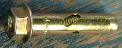
easier method, which I had to use on my own car when this happened to me. I took
a quick trip to the local DIY shop and came up with this :-
It fits the bolt hole perfectly, and once you place it in the hole in the bracket and
line it up with the hole in the chassis you can start screwing the nut up, it
pulls down on the centre tube allowing it to splay out on the inside of the
chassis rail pulling the whole lot up nice and tightly, job done !! A bonus is
that if you need to take the bracket off again all you do is unscrew the nut and
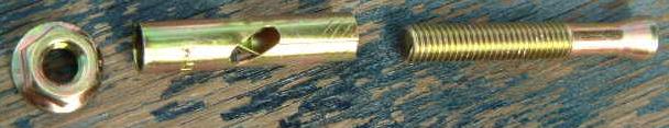
the thread stays where it is ready for next time !! Here is another view of the
bolt which shows it in more detail. :-
If anyone has trouble getting these if they want one let me know, they were only 55p each
too !!!, hope this helps someone out, cheers, Jinxy